

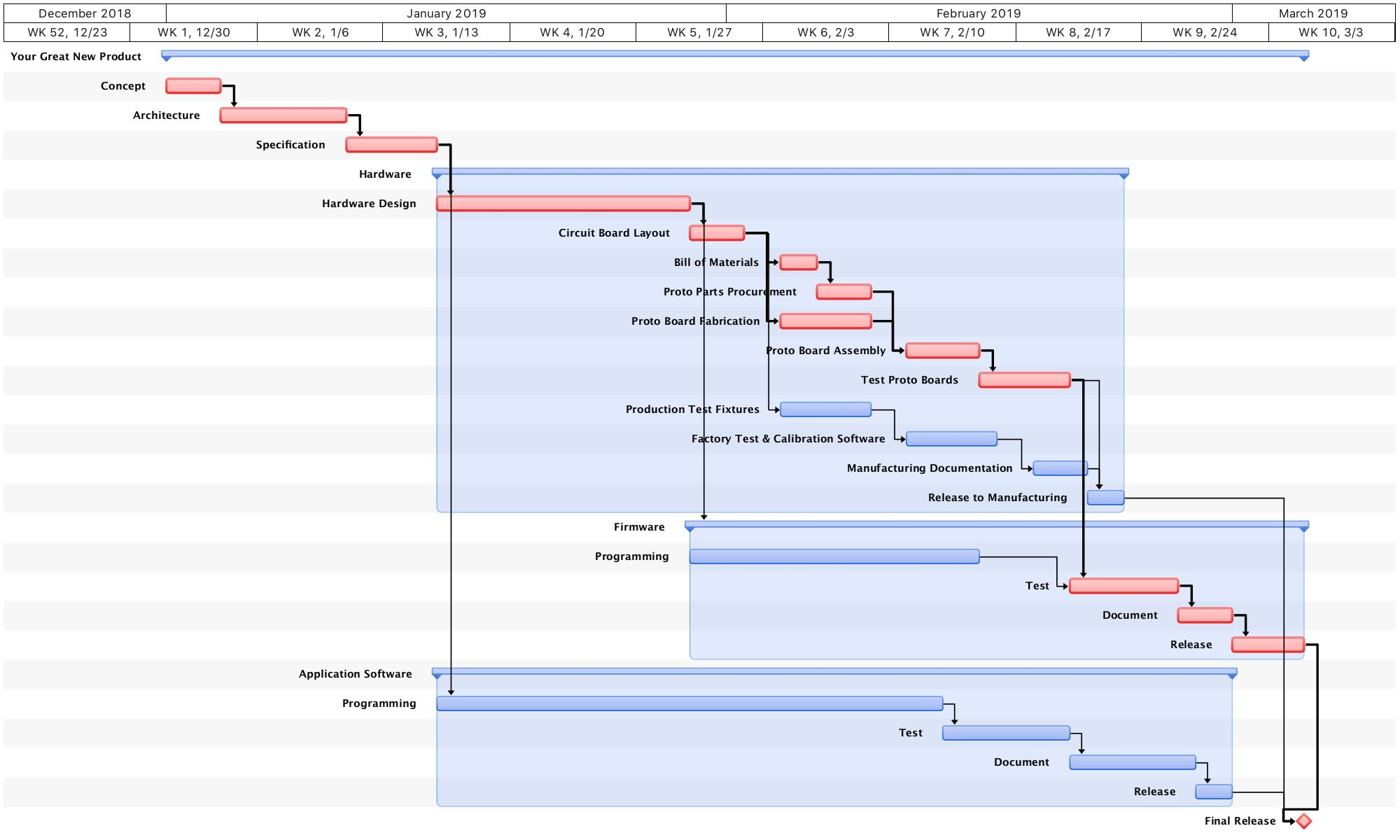
I’m going to walk you through a typical electronic hardware and software product development cycle as shown in the Gantt chart above. Each of the development stages is described below, along with comments on our approach.
Definition Stages
Many engineering and software teams skip these steps and figure it out as they go. When the schedule is tight (as it usually is), they are anxious to dive in and start the “real” work of design and coding. But that can be a big mistake, like traveling without a map and a plan. Sure, you will get there (or somewhere!) eventually. But you might waste time wandering all over the place. And you might miss key steps and features that should have been included and are hard to add later.
Changing your mind in the definition stages is cheap. Changing your mind or having to correct for poor architectural decisions later in a project can be costly. You want to minimize the chances of having to scrap expensive tooling and hardware by more carefully thinking it all through up front. And software changes can be costly too when they involve thousands of lines of code and the changes create a confusing mess.
This is not to say that you might not want to do some rough exploratory designs and prototyping up front to test out some ideas. You can see what is possible, what features make the most sense and do some customer testing to gather valuable feedback. But realize that these are just throwaways and not your final product. It is often better to toss these and start over once the product is fully defined, and incorporate the lessons you’ve learned in the final design.
Think about it. Would you rather tear up a few pages of your plans and start over, or rush in and then have to scrap tens of thousands of dollars of tooling and prototype hardware or time invested in programming? Time spent wisely on the front end can save a lot of time and money in the long run.
Concept
At this stage, you are trying to figure out what the product is and not how to design and make it. Concentrate on the features and goals. Brainstorm. Build some quick mockups. Think about who the target audience is and their needs. Get input from marketing or the customers themselves. Once the concept comes into focus, you should be able to capture it with a few diagrams, a short description, some feature lists or whatever is appropriate.
It is great when I can be involved in this early stage of the development. I can help expand your vision of what is technically possible and create some quick mockups and prototypes. And I have a proven history of innovative ideas to add to yours.
Architecture
In the architectural stage, you are starting to piece together a design, but only in very broad strokes. Think about how all the pieces will fit together at a very high level. And focus on what key pieces of technology you will need, such as special software modules, communications (hardware and protocols), data storage, sensors. Investigate the tradeoffs between different options with an eye towards creating a simple and elegant solution.
A system or product architect should have a broad range of knowledge or experience, the ability to see several steps ahead, and a healthy dose of creativity. This allows them to quickly see the pros and cons of different approaches. And it allows them to see outside the box and bring in ideas that are different than the standard way of doing things. Traditional methods are often the best, but sometimes a simple but key switch in the approach can lead to some big breakthroughs.
This is one of the areas of my work that I am the proudest of, and the huge impact it has made for many of our customers. Click to read blog posts about the significance of a clever architecture in some of our projects and others.
Design Specification
The design specification dives much deeper into the details, typically in a more formal document. Some of the design specifications may be useful in a customer or product specification later, but the main purpose at this point is to guide the developers. Whereas the architectural documents explain to everyone how the main pieces fit together, the design specification tells the engineers and programmers more about how to make it work and their requirements and constraints.
Here are some examples of items to include in a specification:
- Power supply requirements
- Measurement precision and accuracy
- Operating and storage temperatures
- System response times
- Security
- Communication protocols (custom and/or industry standards)
- Data storage
Take more time documenting the different modules and their interactions if they will be assigned to different programmers. This will allow the programmers to work more independently and efficiently. And that saves time and money.
One of the most important parts of this document is the functional specification. It should describe how the product is expected to operate and respond to various conditions and inputs from the user or the rest of the system. And don’t forget to address possible error conditions and how to handle them.
The design specification is often a living document, with additions and changes as the project progresses. Make sure that everyone has access to the latest copy and is aware when changes are made that might affect them. (A version control system can automatically highlight what was changed and when.) Put it in writing rather than relying on verbal communications to make sure everyone is working towards the same goals.
Hardware Path
Hardware Design
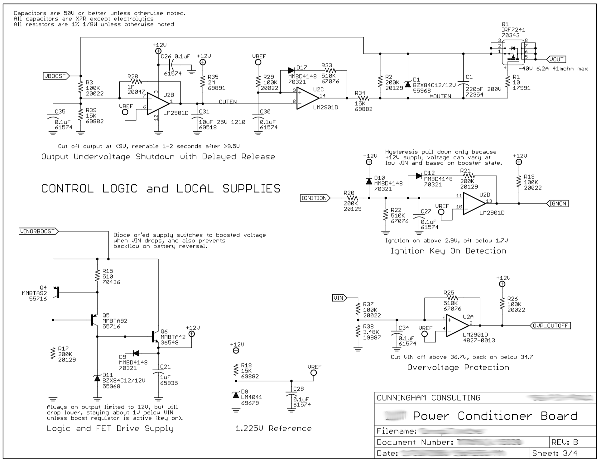
The hardware engineer will create schematics (circuit diagrams) to capture the design. Schematics specify which components (transistors, chips, etc.) are used and how they are connected logically. The engineer may also use circuit simulations at this stage to check and fine-tune the design, especially for analog circuits such as power supplies, amplifiers, and filters.
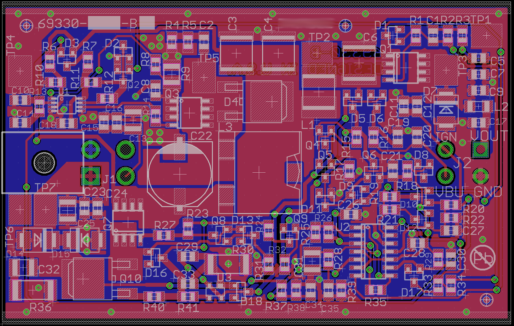
Circuit Board Layout
A schematic represents the logical connections in a circuit. The board layout converts that into a physical design that specifies the board dimensions, where all the parts go on the board, and the routing of the circuit traces that make the physical connections between the pins of the different chips and components.
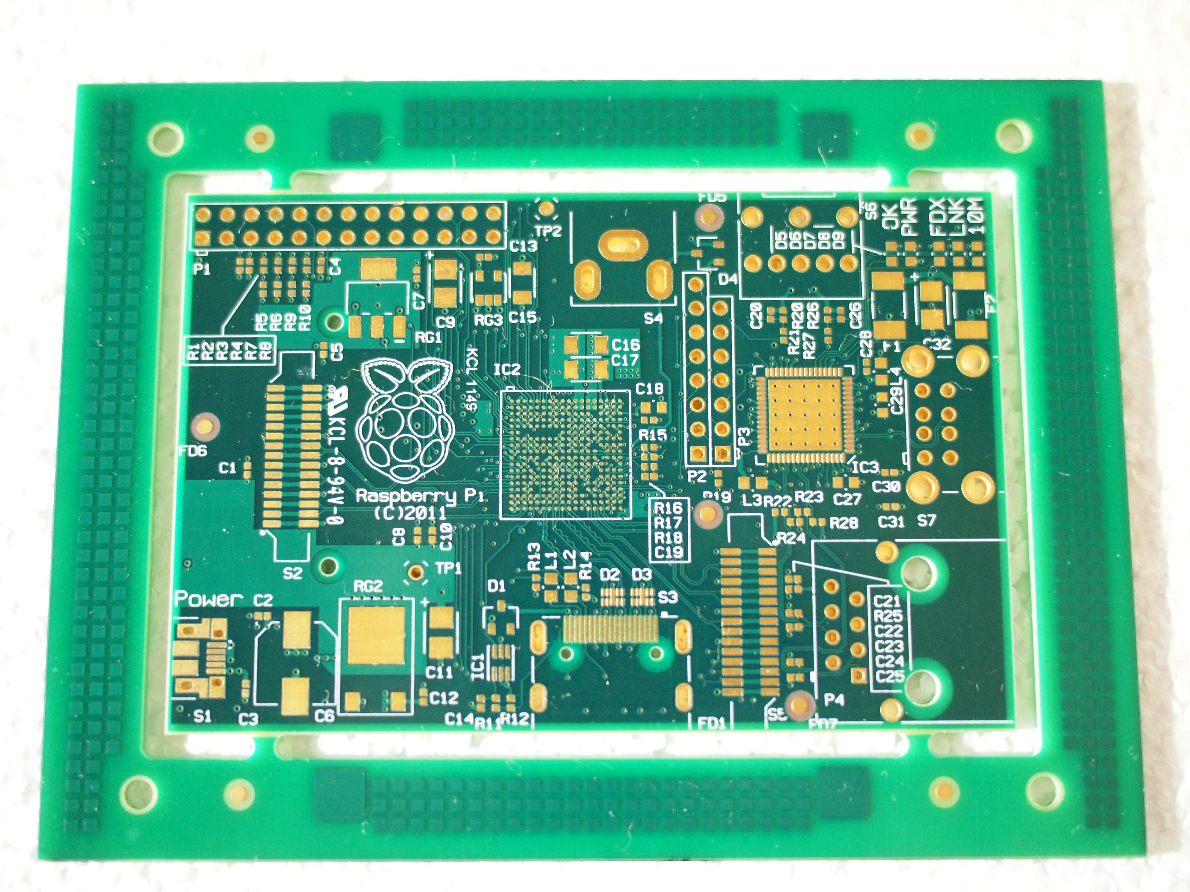
A printed circuit board consists of layers of etched copper traces separated by insulating substrate layers.
The hardware engineer will specify constraints to guide the layout process. These constraints are important to:
- isolate sensitive signals
- minimize noise
- meet timing requirements
- provide adequate current capacity
- isolate analog and digital grounds
- provide proper circuit protections (against ESD and EMI, for example)
- meet mechanical needs such as connector placement
- etc.
The hardware engineer works closely with the person doing the layout and checks and approves their work when done. A mechanical engineer may also be involved to make sure that mounting points, hole sizes and other dimensions match up with the housing where the board will be installed. Some layout issues may arise that require changes in the schematics, such as swapping gates or pins on a chip to improve the signal routing. This close interaction between the two roles often makes it easier and better for me to handle both. My CAD software ties the schematic and layout designs together. And handling both roles lets me quickly see the issues, make decisions and changes on both the schematic and layout and keep the project moving.
A good layout requires the ability to visualize the signal flows around the board and to see ahead to anticipate where the bottlenecks will be so just enough space is left between the parts. Simple boards have just one or two layers of copper signal traces, but many if not most boards have 4, 6, 8 or more layers, like a big 3D puzzle maze. One of the best layout engineers I’ve ever met (and the person who trained me) is also an expert chess player. That ability to see many moves ahead, and analyze all the alternatives, is an important skill.
Each signal is routed through a board by finding the best paths between pads, components and other signals. A signal will often jump back and forth between different layers (using a via) in order to cross over or under other signals and parts in its way. Design rules are set so the software can automatically check your work and make sure the signals don’t get too close to each other, to any pins or the edge of the board.
The CAD programs can also do auto-routing, automatically finding ways to route the signals through the maze. That can save a lot of time, but can also create a mess if not used properly. I find that a combination of manual routing and auto-routing is often the best solution.
Once the layout is complete, the design is ready to be turned into physical circuit boards. Typically a small prototype or pre-production run is made in order to test the design before committing to a larger production order, as described in the following steps.
Bill of Materials
The hardware engineer will create a bill of materials listing all of the parts that will be mounted to the circuit board and any attaching cables and other devices. For a prototype run, they will create a quick list to get the parts ordered for the prototypes. For production, more time is taken to match the parts with the customer’s existing parts management system and part numbers. Alternative parts and multiple source options are also checked and approved in order to give the purchasing and manufacturing departments more flexibility.
Parts Procurement
Your in-house or manufacturer’s purchasing department is skilled at making large purchases at a low price. But it is usually faster and easier for us to handle the purchasing for you for a low volume prototype run. If I am arranging the board fabrication and assembly, I typically have the parts drop shipped to the assembly house or our technicians to save some more time.
Board fabrication
A board fabrication house will take the layout files (mechanical drawings, Gerber files, etc.) and convert them into a physical circuit board. We can work with your in-house or contract manufacturers. But for prototypes our customers often have us arrange this through board manufacturers that specialize in small runs and quick turnaround time.
Automated bare board testing is sometimes used to check for any faulty boards before sending them to the assembly stage. Board faults can include opens and shorts deep within the layers of the board that may be impossible to see or repair from the outside. There might only be one faulty board in a batch (and usually none), but you waste valuable time if that is the one you spend a week building as your first prototype board before you find the problem. Such faults are rare, but if a board has internal layers with fine or tightly spaced signal traces then the chance of faults is higher. If the cost of the following board assembly (labor and parts) is high, then the small cost and extra time to do bare board testing is good insurance. If the board is simple and all the signals are on the outside (1, 2 or 4 layer board) then there is far less risk if this testing is skipped.
Board assembly
Once the bare circuit boards are ready, the circuit components are mounted and soldered onto the board. For surface mount parts (the most common nowadays, as opposed to thru-hole parts), a silkscreen printer deposits a shaped blob of solder paste on all connection pads on the board. Then a high-speed robotic pick and place machine precisely places the miniature components on the board. Reels of tape hold the parts to feed the machine. A robot arm with a tiny vacuum tube uses suction to snatch each part from the tape, move it into position, press it down and then release it. Each leg of the chips and components gets pressed into its own miniature dab of sticky solder paste which will hold it in place temporarily until the solder is melted in the next stage.
We provide the necessary files to the board assembler to create the solder paste silkscreen and to guide the robot part placement. Watch a high-speed pick and place machine in action:
The boards then travel through a wave solder machine or infrared reflow oven (like a fancy Easy-Bake Oven) for soldering. Sometimes there is additional hand soldering of some components.
Machine vision systems and humans check the boards for any misplaced or missing components. And electrical tests are also available to verify all the connections. Some electrical tests require special pads to be included in the design and layout. Electrical tests are sometimes skipped to save money and time on a tight prototype schedule since the boards will be manually tested by the engineer. They can be important for full production runs of some types of boards, however.
board testing
The prototype boards are returned to the hardware designer for careful testing to make sure that the design is right and that it is built properly. If design mistakes are discovered, they are usually fixed through a simple circuit patch. That patch fix is either incorporated into the design of the next iteration of the boards or continues into production. My clients tell me they are amazed at how often my designs work the first time, but mistakes do happen. So testing each board is important before assembling into the final product or larger system.
Production Test fixtures
For larger volume production, test fixtures can streamline testing, programming, and calibration of the boards. We will often create test fixtures, or their precursors, during the prototyping stage. These can then be ruggedized and refined for higher volume production.
These production fixtures might be stand-alone, controlled by a PC, or attached as adapters to more sophisticated generic board testers. Whatever their form, they need to be designed and may involve some sophisticated electronics. I can handle this for you too or provide the specs for your own factory test engineers.
Factory test and calibration software
The factory fixtures for testing, calibration, and programming will also typically need some form of software or configuration. Again, I can provide that service or assist your staff or your manufacturer.
Many of the boards I design have self-test and self-calibration procedures built-in for operation in the field. In that case, then the factory equipment can use or augment that to simplify the factory requirements. For example, the factory setup might provide an accurate reference signal, trigger a calibration, record the results in your database and then tell our firmware to write the manufacturing date, serial numbers and other details in its memory. That setup could be as simple as a PC, a simple program and a serial cable to the product.
Manufacturing documentation
Formal documents are created to record the various factory procedures that have been worked out. These are assembled with all of the other production and design files such as schematics, layout, board fabrication and assembly files, firmware releases, etc.
Release to manufacturing
Once all the documents are in place, I will work with your manufacturing and document control departments to make sure that everything is properly recorded in your systems. And I will be available when full production first starts to help iron out any kinks.
Software and Firmware Paths
The Gantt chart above shows very simplified software and firmware development paths. Typically these are divided up into more steps to highlight and track different modules and functions of the software, and to mark intermediate milestones.
The chart shows an example where the boards have embedded firmware that makes them function, and a companion application is created to talk to the device. For example, this product might be a lab instrument or factory control module. And the software is a PC or web application that provides a user interface to monitor and control the device remotely.
The same basic steps also apply to a software-only project (including the concept, architecture and specification steps that precede these).
Programming
This is the bulk of the work, turning the specification into actual code in whatever programming language is used. Many projects nowadays use several different languages, each with their own specialty, for different parts of the system.
The chart shows the programming, testing, and documentation phases in sequence. But often it is more efficient to do a lot of the work in parallel. For example, you can write test code for a module or routine while or before you write the main code. Then you have a built-in test that tells you immediately if you have made a mistake. And testing small sections of code like this makes it easier to find certain bugs than trying to find the needle in a haystack of thousands of lines of code later.
Similarly, tools exist to allow the programmer to include bits of documentation as specially marked comments throughout the code as they write it. The tools then scan the code and compile the bits into a larger document. Future programmers can then use this document to understand the overall structure and function of the program.
Testing
Thorough testing is important to minimize the chances of any bug getting out to a customer. Testing also is used to compare the operation against the specifications and make sure that all the requirements are met and features are implemented.
The complexity of today’s systems means that sometimes a change in one area might break something else. So it is often worth your time to automate the testing process to make it easy to repeat tests over and over again to not miss anything.
Documentation
As I mentioned earlier, the programmer may scatter documentation fragments throughout the code. These can then be extracted and compiled into a master reference document for programmers.
You may also need documentation written for other audiences such as users (user manuals), management, marketing and so forth.
And don’t forget to record ideas and plans for possible future revisions or additions to the product or product line.
Release
A formal release process is important to ensure that you know exactly what was in the code at that point. This allows you to track changes between different versions for your release announcements. And it allows you to go back in time to track the source of any bugs that might have been introduced.
A release should assign version numbers, and store the present state of the code into a source code management system (also called a version control system). Any user manuals, specification documents, and other affected documents should be revised to match the new features and functionality of the release, and then also stored in the version control system. Record the compiler version and settings so you can fully recreate the release conditions in the future. And if there is a related hardware change, then throw in the revised schematics too. This creates a time capsule of sorts for the whole project.
Final Release
Once all the pieces are complete, and the product is out the door, you can finally wrap things up, celebrate, and prepare for the next project…